> ## Documentation Index
> Fetch the complete documentation index at: https://docs.roboconoxon.org.uk/llms.txt
> Use this file to discover all available pages before exploring further.
# The BrainBox
> The core electronics and software hub for your robot.
The **BrainBox** is the central nervous system of your kit. It contains all the electronics and software needed to power your robot.
 ## Getting Started
### Powering On
1. Take a battery from the kit and plug it into the yellow socket labelled **Battery**.
2. Connect the red "power button" to the black connector along the side of the BrainBox.
3. Press the start button.
4. The battery status LEDs on the front will flash upwards, and the power LED will turn green.
5. When the **User Light** flashes blue, your BrainBox is ready to run code.
The user LED will turn solid while code is currently running.
### Powering Off
When you are finished:
1. Press the power button.
2. The user LED will flash rapidly.
3. Once the LED turns off, you may safely unplug the battery.
***
## Power Distribution
The BrainBox distributes power from the battery to the rest of the robot, providing both **12V** and **5V** outputs.
* **Regulations:** All power must flow through the BrainBox.
* **Safety:** The internal fuse should **never** be replaced.
* **Controls:** Both the On/Off switch and the Start button plug directly into the BrainBox.
## Motors & 12V Power
The BrainBox includes an integrated motor board with the following specifications:
| Condition per channel | Maximum Value |
| :------------------------ | :------------ |
| Continuous current | 10A |
| Peak current (10 seconds) | 30A |
| Operating Voltage | 12V |
**Control Tip:** You can toggle the 12V rail to turn devices on and off easily. Note that toggling this will also cut power to the motor board.
***
## Connectivity & GPIO
### USB
The BrainBox features **one USB port**. If your project requires multiple USB devices (like a camera and a sensor), you will need to use an external USB hub.
### GPIO Output
All GPIO pins are connected in-series with a **1K Ohm resistor** for current limiting. This allows you to connect low-power devices like LEDs directly to the pins.
While they nominally operate at 5V, the true output varies based on your load. You can calculate the voltage across your load using the following formula:
$V_{load} = (5 * R_{load}) / (R_{load} + 1000)$
**Limits:** Do not sink or source more than **25mA** into the GPIO pins, as this may damage internal components.
### GPIO Input
We advise against using analogue inputs with an impedance greater than **9K Ohms**. High impedance can result in inaccurate readings. If you must use a high-impedance source, use an **Op-amp** to buffer the input.
***
## PWM (Pulse Width Modulation)
PWM is used to signal devices on how much "output" to provide—such as motor speed or servo position—by varying the width of electrical pulses.
Note: PWM pins cannot drive large motors directly; they supply a maximum of **3A at 5V**.
### PWM Signal Ranges
| Value | Pulse Length |
| :---- | :-------------- |
| 178 | 2.39ms |
| 100 | 2ms |
| 0 | 1.5ms (Neutral) |
| -100 | 1ms |
| -178 | 0.61ms |
***
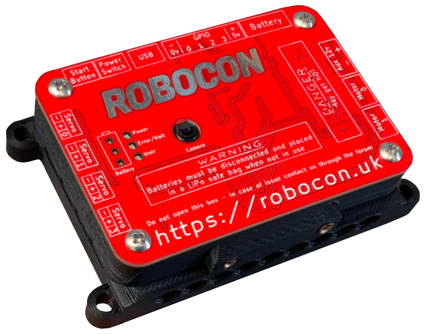
## Pinout Diagrams
### IO Layout
## Getting Started
### Powering On
1. Take a battery from the kit and plug it into the yellow socket labelled **Battery**.
2. Connect the red "power button" to the black connector along the side of the BrainBox.
3. Press the start button.
4. The battery status LEDs on the front will flash upwards, and the power LED will turn green.
5. When the **User Light** flashes blue, your BrainBox is ready to run code.
The user LED will turn solid while code is currently running.
### Powering Off
When you are finished:
1. Press the power button.
2. The user LED will flash rapidly.
3. Once the LED turns off, you may safely unplug the battery.
***
## Power Distribution
The BrainBox distributes power from the battery to the rest of the robot, providing both **12V** and **5V** outputs.
* **Regulations:** All power must flow through the BrainBox.
* **Safety:** The internal fuse should **never** be replaced.
* **Controls:** Both the On/Off switch and the Start button plug directly into the BrainBox.
## Motors & 12V Power
The BrainBox includes an integrated motor board with the following specifications:
| Condition per channel | Maximum Value |
| :------------------------ | :------------ |
| Continuous current | 10A |
| Peak current (10 seconds) | 30A |
| Operating Voltage | 12V |
**Control Tip:** You can toggle the 12V rail to turn devices on and off easily. Note that toggling this will also cut power to the motor board.
***
## Connectivity & GPIO
### USB
The BrainBox features **one USB port**. If your project requires multiple USB devices (like a camera and a sensor), you will need to use an external USB hub.
### GPIO Output
All GPIO pins are connected in-series with a **1K Ohm resistor** for current limiting. This allows you to connect low-power devices like LEDs directly to the pins.
While they nominally operate at 5V, the true output varies based on your load. You can calculate the voltage across your load using the following formula:
$V_{load} = (5 * R_{load}) / (R_{load} + 1000)$
**Limits:** Do not sink or source more than **25mA** into the GPIO pins, as this may damage internal components.
### GPIO Input
We advise against using analogue inputs with an impedance greater than **9K Ohms**. High impedance can result in inaccurate readings. If you must use a high-impedance source, use an **Op-amp** to buffer the input.
***
## PWM (Pulse Width Modulation)
PWM is used to signal devices on how much "output" to provide—such as motor speed or servo position—by varying the width of electrical pulses.
Note: PWM pins cannot drive large motors directly; they supply a maximum of **3A at 5V**.
### PWM Signal Ranges
| Value | Pulse Length |
| :---- | :-------------- |
| 178 | 2.39ms |
| 100 | 2ms |
| 0 | 1.5ms (Neutral) |
| -100 | 1ms |
| -178 | 0.61ms |
***
## Pinout Diagrams
### IO Layout
 ### Motor Connections
 ### Front Panel
